
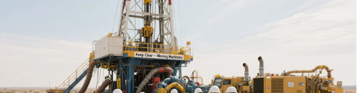
In the fast-paced environment of the Permian Basin, clear communication is the backbone of a safe and efficient job site.
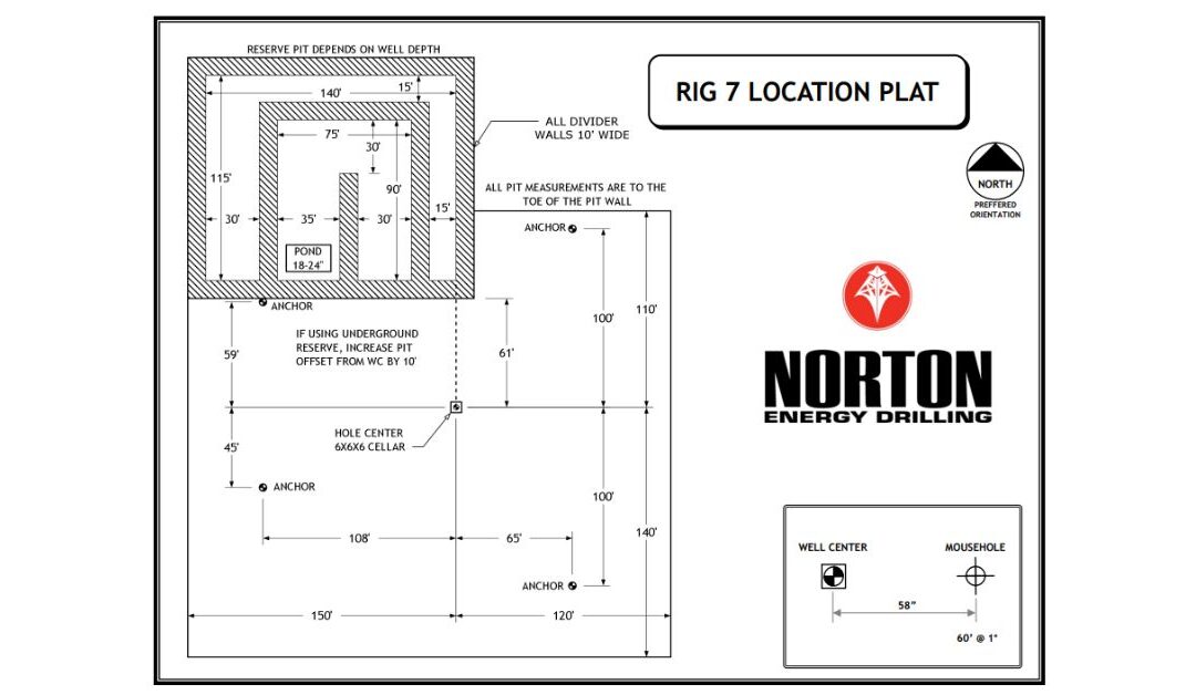
One of the most important documents you’ll see before a bit ever touches the ground is the Drilling rig plat diagram
(often called a “rig layout” or “site plan”).
Whether you’re a client representative overseeing the project, an HSE professional planning muster points, or a logistics coordinator
managing deliveries, understanding how to read these diagrams helps teams plan, coordinate, and execute with confidence.
Using a standard layout—like the type included in a Norton Energy rig plat—as a light reference, this guide breaks the process into
field-practical steps.
What a drilling rig plat diagram is (and what it isn’t)

A drilling rig plat diagram is a high-level drawing that shows where major rig and support systems are positioned on location.
It’s designed to answer practical questions such as: “What goes where?”, “How much space do we need?”, and “How will equipment and people move safely?”
What it isn’t: it’s not a complete engineering package, not a substitute for the pre-job safety meeting, and not the only source
of truth for underground utilities, pad construction constraints, or every hazard on site. It’s a planning tool that supports alignment across
operations, safety, and logistics.
Field rule of thumb: treat the plat as your shared “map” for coordination—then confirm details during pre-job planning and on-site verification.
Want a bigger-picture view of what different rig types look like in the field (and why layouts vary)? Go read Types of Oil Drilling Rigs.
What questions a plat should help you answer
Before you zoom into equipment shapes and dimensions, step back and ask what the plat should make clear to everyone involved.
A strong drilling rig plat diagram typically helps you answer:
- Fit: Does the rig and support footprint fit the pad and lease boundaries?
- Orientation: Which way is the rig facing and how does that affect pipe handling and traffic flow?
- Access: Where do deliveries enter/exit and where can trucks safely stage or turn around?
- Interfaces: Where do third-party services tie in (fuel, water, waste, cranes, etc.)?
- Safety: Where are higher-risk areas and how do we keep foot traffic and vehicle traffic separated?If you can’t answer these quickly from the drawing, it’s a sign the team needs clarification before move-in starts.
If you’re aligning layout decisions with program goals, timelines, and stakeholder coordination, go read Oil Drilling Project Management.
How to read a Drilling Rig Plat Diagram in 6 steps

You don’t need to be a draftsman to read a rig plat. Use this six-step scan to understand the plan quickly and spot issues early.
1) Start with the title block and revision date
The title block (often in a corner of the drawing) usually includes the rig name/identifier, document title, and revision date.
Layouts can change due to pad dimensions, client requirements, or updated equipment configuration—so revision control matters.
2) Confirm orientation
Find the north arrow or directional reference. This tells you how the drawing aligns with the real world.
Orientation affects everything from where the V-door faces to where traffic should flow.
3) Check scale and critical dimensions
Look for a scale bar or dimension callouts. Confirm the overall footprint and any marked clearances.
When in doubt, focus on the constraints that drive problems in the field: turning room, working clearances, and separation between key systems.
4) Locate the “heart” of operations: well center and rig floor
The well center is typically the anchor point. From there, identify the rig floor/substructure area and the general “front/back” of the rig.
Knowing the functional front (often tied to pipe handling direction) helps you anticipate where pipe racks, catwalks, and staging will live.
5) Map support systems: mud, power, and storage
Most plats show blocks for major support systems such as the mud system, tanks, generators/power house, and other infrastructure.
Your goal here is to understand adjacency (what sits next to what), and access (what needs frequent servicing).
For example, fuel and water systems should be positioned so trucks can safely reach them without cutting through restricted areas.
6) Trace logistics flow and identify safety-sensitive zones
Finally, “walk the map.” Imagine a fuel truck arriving, a tubular delivery unloading, and a crew member walking from a trailer to the rig floor.
Are there clear routes? Are pedestrians separated from vehicles? Are high-activity areas identified and controlled?
Practical approach: read the plat like a traffic plan—if people and equipment will cross paths, make sure it’s intentional, controlled, and clearly communicated.
If you want a safety-first companion to the step-by-step mindset—especially for pre-job planning—go read Oil Drilling Ultimate 7 Safety Tips.
The “Before You Sign Off” checklist

Before approving a layout—or before move-in begins—use this quick checklist to reduce surprises on location.
It’s designed for “all of the above” stakeholders: client reps, HSE, and logistics.
- Revision check: Is this the latest version of the plat?
- Pad fit: Does the full footprint fit inside lease boundaries and planned pad limits?
- Access routes: Is there a clear in/out route for vendors (fuel, water, waste, etc.)?
- Pipe handling direction: Does the orientation support safe and efficient tubular handling?
- Separation and clearances: Are key areas spaced appropriately for safe operations and servicing?
- Traffic vs. footpaths: Are pedestrian routes kept away from heavy-vehicle routes where possible?
- Known constraints: Are overhead/underground hazards and pad constraints accounted for in planning?If you’re making last-minute layout changes on location, you’re paying for it in time, risk, and avoidable confusion. Catch issues at the plat stage.
For a deeper look at hazards your final layout review should help reduce, go read Safety Risks in Oil Drilling Rigs Operation.
Conclusion
A drilling rig plat diagram is more than a drawing—it’s a shared reference that helps multiple teams align on how the location will function.
When you read it systematically—revision, orientation, scale, core systems, logistics flow, and safety zones—you reduce the odds of rework,
delays, and preventable safety exposure once operations begin.
If you’d like help interpreting a plat for your specific pad constraints and project needs, the Norton Energy team can walk through the layout
and coordinate practical next steps.
Need to discuss a drilling program or rig planning needs? Contact Norton Energy.
If you want to see how modern drilling is evolving—and why that changes layouts, workflows, and planning—go read The Future of Drilling Technology.

For a broader safety framework that supports rig planning and on-location operations, refer to API’s guidance on occupational safety for onshore drilling and servicing.
Recent Comments